Fill a Valid Electrical Panel Schedule Template
The Electrical Panel Schedule form is an essential tool for anyone involved in electrical installations or maintenance. It serves as a comprehensive overview of the electrical distribution system within a building, detailing the circuits, their loads, and the associated breakers. This form not only helps in organizing the electrical layout but also plays a crucial role in ensuring safety and compliance with local codes. By clearly outlining each circuit's purpose and its amperage, the schedule aids electricians in troubleshooting issues efficiently. Moreover, it provides valuable information for future upgrades or modifications, making it easier to manage electrical resources effectively. Understanding how to fill out and utilize this form can streamline operations and enhance safety in any electrical project.
Additional PDF Templates
Example of Birth Certificate - Accurate entries on the Certificate of Live Birth help ensure a child's access to healthcare.
CBP Form 6059B - Providing detailed information on the CBP 6059B can help avoid unnecessary inspections.
Creating a corporation in Missouri necessitates the completion of essential legal documentation, notably the Articles of Incorporation, which serves as a formal declaration of the company's name, purpose, and the details of its organizers, marking the initial step towards establishing a business within the state.
What Is Immunization Records - It supports the child's health and educational needs effectively.
Similar forms
The Electrical Panel Schedule form is an important document used in electrical engineering and construction. It provides a detailed overview of the electrical distribution system within a building. Several other documents serve similar purposes, helping to ensure that electrical systems are designed, installed, and maintained correctly. Below are five documents that share similarities with the Electrical Panel Schedule form:
- Load Calculation Sheet: This document outlines the expected electrical load for various circuits and equipment. Like the Electrical Panel Schedule, it helps ensure that the electrical system can handle the demands placed on it.
- Trailer Bill of Sale Form: To properly document your trailer transactions, consider the required trailer bill of sale information to ensure a smooth transfer of ownership.
- Circuit Directory: A circuit directory lists all the circuits in an electrical panel, detailing their respective loads and locations. Similar to the Electrical Panel Schedule, it provides essential information for identifying and managing electrical circuits.
- Single-Line Diagram: This diagram presents a simplified representation of the electrical system, showing how various components are interconnected. It serves a similar purpose by providing a clear overview of the electrical distribution, much like the Electrical Panel Schedule.
- Wiring Diagram: A wiring diagram offers a detailed visual representation of the electrical connections and components within a system. It shares similarities with the Electrical Panel Schedule by illustrating how circuits are wired and connected to the panel.
- As-Built Drawings: These drawings reflect the actual construction of the electrical system after installation. They are similar to the Electrical Panel Schedule in that they provide a record of the installed system, ensuring that future maintenance and modifications can be carried out effectively.
Document Specifics
| Fact Name | Description |
|---|---|
| Purpose | The Electrical Panel Schedule form is used to document the layout and specifications of electrical circuits in a building, ensuring proper distribution and safety of electrical power. |
| Components | This form typically includes information such as circuit numbers, load calculations, and panel ratings, which help in identifying the electrical load and ensuring compliance with safety standards. |
| Regulatory Compliance | In many states, the use of an Electrical Panel Schedule is governed by the National Electrical Code (NEC) and local building codes, which mandate proper documentation for safety and efficiency. |
| Importance | Accurate completion of the Electrical Panel Schedule is crucial for electricians and inspectors, as it aids in troubleshooting and maintaining electrical systems effectively. |
Things You Should Know About This Form
-
What is an Electrical Panel Schedule form?
The Electrical Panel Schedule form is a document that outlines the distribution of electrical circuits within a panel. It provides a detailed list of all circuits, their corresponding breakers, and the loads they serve. This form is essential for ensuring proper electrical management and safety in residential, commercial, and industrial settings.
-
Why is it important to have an updated Electrical Panel Schedule?
An updated Electrical Panel Schedule is crucial for several reasons. First, it helps in identifying the capacity and load of each circuit, which is vital for preventing overloads. Second, in the event of an electrical failure or emergency, having an accurate schedule allows for quicker troubleshooting and repairs. Lastly, it is often required for compliance with local electrical codes and regulations.
-
How can I create an Electrical Panel Schedule?
Creating an Electrical Panel Schedule involves several steps. Start by gathering information about all circuits connected to the panel. This includes the circuit numbers, breaker sizes, and the specific loads each circuit serves. Next, organize this information in a clear format, typically in a table layout. Each entry should include the circuit number, breaker size, load description, and any additional notes relevant to the circuit. Finally, review the completed schedule for accuracy and ensure it is easily accessible for future reference.
-
Who should maintain the Electrical Panel Schedule?
The responsibility for maintaining the Electrical Panel Schedule typically falls on the facility manager or the electrician in charge of the electrical system. Regular updates should be made whenever there are changes to the electrical system, such as adding new circuits or modifying existing ones. It is also advisable for building owners and managers to periodically review the schedule to ensure it remains current and accurate.
Documents used along the form
The Electrical Panel Schedule form is an essential document for managing electrical systems in buildings. However, it often works in conjunction with several other forms and documents to ensure a comprehensive understanding of electrical installations and safety protocols. Below are some commonly used forms that complement the Electrical Panel Schedule.
- Load Calculation Worksheet: This document helps determine the total electrical load of a building. It accounts for all electrical appliances and systems, ensuring the electrical panel can handle the demand safely.
- Hold Harmless Agreement: This document safeguards one party from liability for injuries or damages incurred by another party, ensuring a risk-free engagement in various transactions. It is crucial for compliance with local laws, particularly in Alabama, as outlined in the Hold Harmless Agreement.
- Service Entrance Diagram: This diagram outlines the main service entrance of the electrical system. It shows how power enters the building and connects to the electrical panel, providing a visual representation of the setup.
- Electrical One-Line Diagram: This simplified drawing illustrates the electrical distribution system. It highlights the connections between components, making it easier to understand the flow of electricity through the system.
- Panelboard Schedule: Similar to the Electrical Panel Schedule, this document details the circuits within a panelboard. It lists circuit numbers, loads, and the devices connected, helping with organization and maintenance.
- Inspection Checklist: This checklist is used during inspections to ensure all electrical systems meet safety standards. It helps identify any potential issues that need addressing before the system is approved for use.
Each of these documents plays a crucial role in the overall management and safety of electrical systems. Together, they provide a thorough understanding of the electrical infrastructure, ensuring that everything operates efficiently and safely.
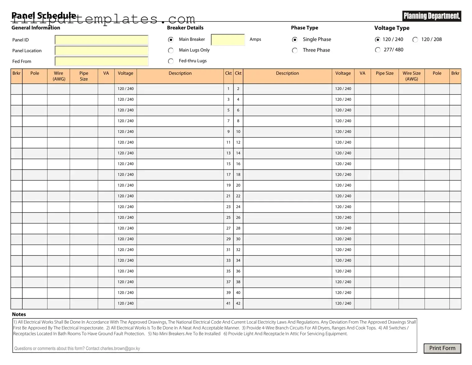
Electrical Panel Schedule Preview
Panel Schedule
General Information
Panel ID
Panel Location
Fed From
Breaker Details
Main Breaker
Main Lugs Only
|
Phase Type |
Voltage Type |
|
Amps |
Single Phase |
120 / 240 |
120 / 208 |
|
Three Phase |
277/ 480 |
120 / 240 |
|
|
|
Brkr |
Pole |
Wire |
Pipe |
VA |
Voltage |
Description |
Ckt |
Ckt |
Description |
Voltage |
VA |
Pipe Size |
Wire Size |
Pole |
Brkr |
|
|
(AWG) |
Size |
|
|
|
|
|
|
|
|
|
(AWG) |
|
|
|
|
|
|
|
|
|
|
|
|
|
|
|
|
|
|
|
|
|
|
|
120 / 240 |
|
1 |
2 |
|
120 / 240 |
|
|
|
|
|
|
|
|
|
|
|
|
|
|
|
|
|
|
|
|
|
|
|
|
|
|
120 / 240 |
|
3 |
4 |
|
120 / 240 |
|
|
|
|
|
|
|
|
|
|
|
|
|
|
|
|
|
|
|
|
|
|
|
|
|
|
120 / 240 |
|
5 |
6 |
|
120 / 240 |
|
|
|
|
|
|
|
|
|
|
|
|
|
|
|
|
|
|
|
|
|
|
|
|
|
|
120 / 240 |
|
7 |
8 |
|
120 / 240 |
|
|
|
|
|
|
|
|
|
|
|
|
|
|
|
|
|
|
|
|
|
|
|
|
|
|
120 / 240 |
|
9 |
10 |
|
120 / 240 |
|
|
|
|
|
|
|
|
|
|
|
|
|
|
|
|
|
|
|
|
|
|
|
|
|
|
120 / 240 |
|
11 |
12 |
|
120 / 240 |
|
|
|
|
|
|
|
|
|
|
|
|
|
|
|
|
|
|
|
|
|
|
|
|
|
|
120 / 240 |
|
13 |
14 |
|
120 / 240 |
|
|
|
|
|
|
|
|
|
|
|
|
|
|
|
|
|
|
|
|
|
|
|
|
|
|
120 / 240 |
|
15 |
16 |
|
120 / 240 |
|
|
|
|
|
|
|
|
|
|
|
|
|
|
|
|
|
|
|
|
|
|
|
|
|
|
120 / 240 |
|
17 |
18 |
|
120 / 240 |
|
|
|
|
|
|
|
|
|
|
|
|
|
|
|
|
|
|
|
|
|
|
|
|
|
|
120 / 240 |
|
19 |
20 |
|
120 / 240 |
|
|
|
|
|
|
|
|
|
|
|
|
|
|
|
|
|
|
|
|
|
|
|
|
|
|
120 / 240 |
|
21 |
22 |
|
120 / 240 |
|
|
|
|
|
|
|
|
|
|
|
|
|
|
|
|
|
|
|
|
|
|
|
|
|
|
120 / 240 |
|
23 |
24 |
|
120 / 240 |
|
|
|
|
|
|
|
|
|
|
|
|
|
|
|
|
|
|
|
|
|
|
|
|
|
|
120 / 240 |
|
25 |
26 |
|
120 / 240 |
|
|
|
|
|
|
|
|
|
|
|
|
|
|
|
|
|
|
|
|
|
|
|
|
|
|
120 / 240 |
|
27 |
28 |
|
120 / 240 |
|
|
|
|
|
|
|
|
|
|
|
|
|
|
|
|
|
|
|
|
|
|
|
|
|
|
120 / 240 |
|
29 |
30 |
|
120 / 240 |
|
|
|
|
|
|
|
|
|
|
|
|
|
|
|
|
|
|
|
|
|
|
|
|
|
|
120 / 240 |
|
31 |
32 |
|
120 / 240 |
|
|
|
|
|
|
|
|
|
|
|
|
|
|
|
|
|
|
|
|
|
|
|
|
|
|
120 / 240 |
|
33 |
34 |
|
120 / 240 |
|
|
|
|
|
|
|
|
|
|
|
|
|
|
|
|
|
|
|
|
|
|
|
|
|
|
120 / 240 |
|
35 |
36 |
|
120 / 240 |
|
|
|
|
|
|
|
|
|
|
|
|
|
|
|
|
|
|
|
|
|
|
|
|
|
|
120 / 240 |
|
37 |
38 |
|
120 / 240 |
|
|
|
|
|
|
|
|
|
|
|
|
|
|
|
|
|
|
|
|
|
|
|
|
|
|
120 / 240 |
|
39 |
40 |
|
120 / 240 |
|
|
|
|
|
|
|
|
|
|
|
|
|
|
|
|
|
|
|
|
|
|
|
|
|
|
120 / 240 |
|
41 |
42 |
|
120 / 240 |
|
|
|
|
|
|
|
|
|
|
|
|
|
|
|
|
|
|
|
|
|
Notes
1)All Electrical Works Shall Be Done In Accordance With The Approved Drawings, The National Electrical Code And Current Local Electricity Laws And Regulations. Any Deviation From The Approved Drawings Shall First Be Approved By The Electrical Inspectorate. 2) All Electrical Works Is To Be Done In A Neat And Acceptable Manner. 3) Provide
Receptacles Located In Bath Rooms To Have Ground Fault Protection. 5) No Mini Breakers Are To Be Installed 6) Provide Light And Receptacle In Attic For Servicing Equipment.
Questions or comments about this form? Contact charles.brown@gov.ky
Print Form